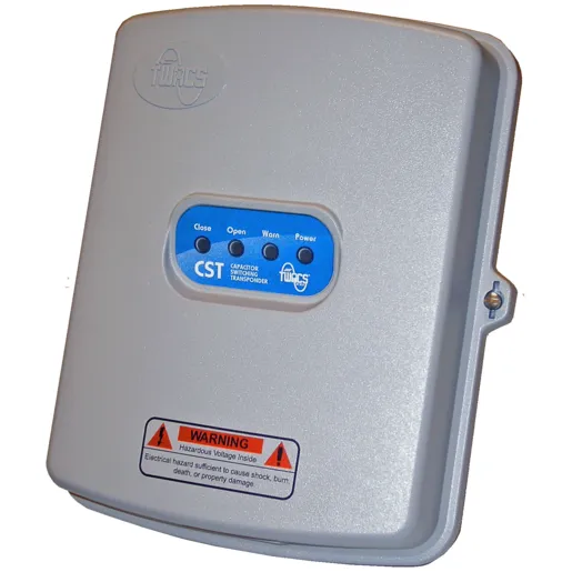

Capacitor Switching Transponder (CST)
Brand: Aclara
Expertise You Can Trust. Built using the extensive knowledge of Hubbell and Aclara engineering teams, TWACS® CSTs are installed on capacitor banks enabling visibility and control of your distribution network.
Reliably and efficiently control your Smart Grid using Aclara’s TWACS CST to automate voltage regulation and power quality management. Multiple data feeds and applications can integrate through Aclara ONE platform to automatically control capacitor banks and other relay-switched devices.
- Automate remote management of capacitor banks and other distribution automation devices
- Obtain on-demand status information for troubleshooting, alarms, voltage profiles and switch status
- Reduce overhead related to capacitor bank patrols and line loss
- Eliminate manual switching
- Monitor neutral currents to pinpoint partial bank failures or blown fuses
- Includes local/remote door interlocking and configurable open/close timers and alarming
Product details
General
Communication Method
Aclara TWACS® PLC
Emission Regulations
- EMI/RFI Emission conducted radiated: Class A, 47CFR Part 15 Subpart J (meets Class B limits) All wiring: 5' length in grounded conduit US: FCC Part 15, Class B per ANSI C12.1-2001Test No. 27 - “Radio Frequency Conducted and RadiatedEmissions”
- EMI/RFI Susceptibility: IEC 61000-4-3; 2002 Radiated, RF, electromagnetic field immunity and IEC 61000-4-6;2006: Immunity to conducted disturbances, induced by RF fields. 30 Volts/meter, MIL-STD-461/462, 150 kHz - 10 GHz; 80% modulation
- Vertical and horizontal polarization; no misoperation or loss of data allowed US: Per ANSI C12.1-2001Test No. 26- “Effect of Radio Frequency Interference” Canada: MIL-STD-461B per CAN3-C17-M84
Ingress Protection
IP66 per IEC 60529
Life Expectancy
15+ years
Material
UV stabilized polycarbonate
Mounting Type
4-jaw or 6-jaw meter socket
Operating Temperature
- -40°C to +60 °C (-40°F to +140°F)
- Complies with IEEE 495 Temperature
- Cycling Test to +85 °C
Power Supply
120VAC +15% / -20%
Storage Temperature Range
-40°C to +85°C (-40°F to +185°F)
Surge Protection
- AC Line Surge: Category C, Common and Transverse, ring wave and bi-wave; no misoperation or loss of data allowed US: ANSI/IEEE C62.41-2002 per ANSI C12.1-2001 Canada: ANSI/IEEE C62.41 per CAN3-C17-M84
- Surge Withstand Capability: ANSI/IEEE C37.90.1-2002 Electrical Fast Transient 2.5kHz at 4kV Oscillatory 1MHz and 2.5kV, 2500 V, Common mode and differential mode; applied per Southern California Edison's requirements; no misoperation or loss of data allowed US: ANSI/IEEE C37.90.1-2002 Canada: ANSI/IEEE C37.90 per CAN3-C17-M84
Dimensions
Depth
4 in
Height
10 in
Weight
2 lb
Width
8 in
Electrical Ratings
Current Rating
34 A RMS, Inbound signaling @ 120VAC A
Dielectric Strength
High Voltage Isolation on Meter Chassis: Dielectric Withstand (Insulation) US: Insulation High Potential (Hi-Pot) test of 2500 Vrms between all high voltage inputs and the meter chassis, applied for 1 minute, per ANSI C12.1-200; Canada: Same as above per CAN3-C17-M84
Frequency Rating
60Hz +/- 2.0%
Voltage - Radio Interference
Voltage Interruption Test US: Per ANSI C12.1-2001, Test No. 16
Voltage Rating
120VAC +15% / -20%
Withstand Current - Short Time (2 sec)
Electrical Fast Transient Withstand: 4000 V, Unidirectional wave Rise time < 5 nanoseconds Crest time > 50 nanoseconds 2 seconds @ 60 pulses / second No misoperation or loss of data allowed US: IEEE/ANSI C37.90.1-2002