Transcript
00:00Welcome to Acme Electrics Virtual Transformer seminar.
00:04In this session, we will be discussing buck boost transformers.
00:11Buck boost transformers start out as isolation transformers with outputs from 12 to 48 volts
00:17which get field connected as auto transformers to increase or decrease voltage within a range
00:23of 5 to 20%. For example, 208 volts to 230 volts.
00:28When field connected as auto transformers, the secondary voltage adds to or subtracts from the
00:34supply voltage.
00:36They do not provide isolation from the supply because they are auto connected during
00:40installation. Let's quickly review the difference between an
00:44isolated and auto transformer.
00:48An isolation transformer is one in which the secondary winding is isolated or insulated from
00:54the primary winding.
00:55It may or may not contain an electrostatic shield between the windings.
00:59An auto transformer is one in which the secondary and primary windings are electrically
01:04connected to each other. Buck boost transformers come out of the box as
01:08an isolation transformer but get field connected to become an auto transformer.
01:14The major advantages of auto transformers are that they are smaller in size,
01:19lighter and less expensive than comparable isolation units
01:27here we see the principle that is the basis for understanding the operation of buck boost
01:32transformers when current flowing in a single conductor reaches a point where it can divide
01:37and now flow in two separate conductors. How will it divide?
01:42It will divide based on the ratio of the resistances of the two wires?
01:46If the conductors are the same resistance or size, then the current will divide 50% and 50%.
01:53If one conductor is twice as large as the other, then the current will divide 66.6% and
01:5933.3%.
02:01If one is three times as large as the other, then the current will divide 75% and 25% and so
02:08forth. This condition is what we have.
02:10When we auto connect the buck boost transformer by connecting a smaller primary wire to a
02:16larger secondary wire, the larger wire will carry the most current.
02:25In this example, a transformer rated one KB on the nameplate means that the primary and
02:31secondary windings are each rated at one K va one KB equals 1000 va 1000
02:38va divided by 100 volts equals 10 amps, 1000 va divided by 10 volts equals
02:44100 amps.
02:46Note that in any circuit, the input K va will be equal to the output K va.
02:55In a boosting configuration, the windings are series connected so that the primary and
03:00secondary voltages will be added when auton connected the 100 volt primary and 10 volt
03:06secondary add together to deliver 110 volts out
03:15in this configuration, the one KB A rating is increased to 11 KB A.
03:20As a result of the auto connection, the new KB A equals the output volts multiplied by the
03:27rated secondary winding amps divided by 1000.
03:30This gives us 110 multiplied by 100 divided by 1000, giving us
03:3711 K VA since input and output K VA are the same, the input amps would be 11
03:44K VA divided by 100 volts giving us 110 amps. You may wonder how can
03:51this transformer with a primary, only rated for 10 amps handle this 110 amps of current?
03:58It actually doesn't because where we joined the primary and secondary windings,
04:03the 110 amps divides into 100 amps in the secondary and only 10 amps in the primary.
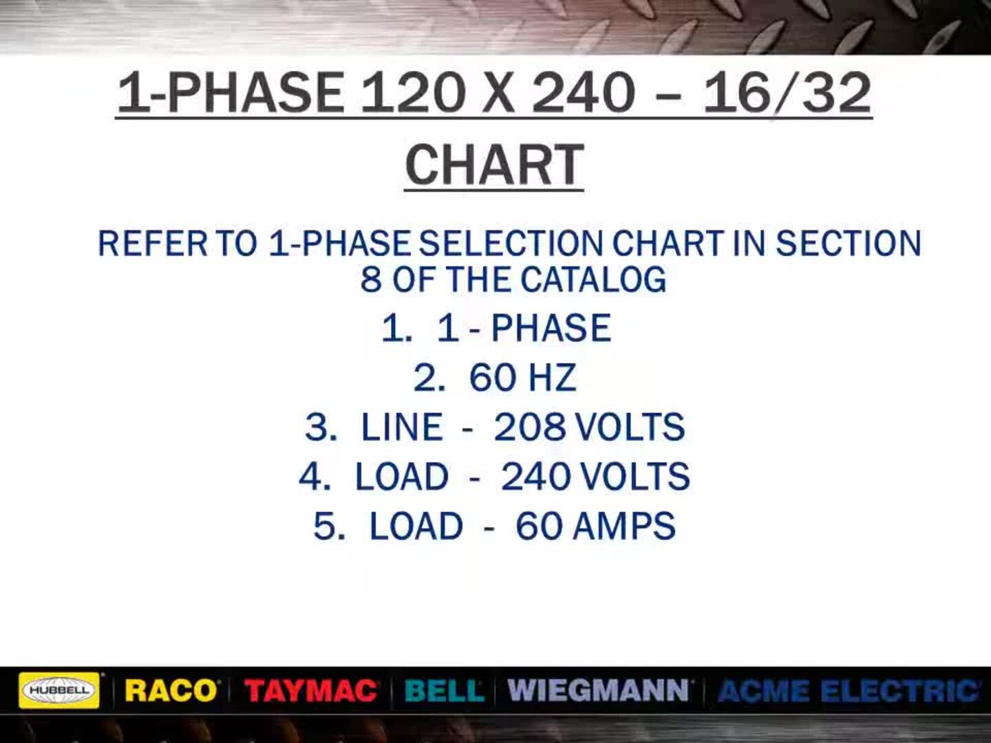
04:14In order to select your buck boost transformer, you will need to know the system phase,
04:19the system frequency, the line voltage, the load voltage and the load KV amps or
04:26horsepower. You can review information in our catalog about
04:29selecting the proper buck boost transformer. You can review the selection charts identifying
04:35differences between voltages and also between single and three phase.
04:39If load is given in horsepower, you must first use tables two or four from section one of our
04:45catalog. For best results, the line voltage should be
04:48the actual measured voltage and not the nominal circuit rating.
04:56Here, we have example, one, you would turn to the single face selection tables and find line
05:02and load voltages across the top of the chart.
05:05If you do not find the exact voltages determine which ground to use by finding the difference
05:10between the line and load volts. In this example,
05:14189 volts subtracted from 208 volts equals 19 volts compare with the secondary
05:20voltage of each group for the nearest equal to or greater than value.
05:28When viewing the single face selection tables in the ACME catalog,
05:32select the desired line and load voltage combination across the top of the chart.
05:37Since the load was stated in KB, you would read down the column to the desired KB rating.
05:43If the exact value is not found, go to the next higher value read to the far left to get the
05:49correct catalog number.
05:51In our example here, the item number used would be T 181051,
05:57go back to the desired voltage column and read down to the bottom to find the correct wiring
06:02diagram. Here we see that input is applied
06:09to primary winding only and that output is across both primary and secondary as stated
06:15previously output minus input equals voltage of secondary winding.
06:20In our example, we are applying 189 volts to a 240 volt winding or
06:2778.7% of rated voltage.
06:30Since transformers are just ratio devices, we will get 78.7% of the secondary rated voltage.
06:37In this case, 78.7% of 24 volts equals 18.9 volts.
06:43Boosting output will equal input 189 volts plus secondary volts.
06:4918.9 volts for a total of 208 volts.
06:57In this example, number two, we would take the 208 volts and subtract from the 240 volts to
07:03get 32 volts.
07:08Again, we would find the single face selection tables in the ACME catalog and select the
07:13desired line and load voltage combination across the top of the chart reading down the
07:18column. Until you find a value of 60 amps or greater,
07:21you will find 62.5 amps reading to the far left. We would find item number T
07:27113075.
07:33In this example, we are applying 208 volts to a 240 volt winding or
07:3986.6% of rated voltage.
07:42Since the secondary of this unit is rated at 32 volts, we will only get 86.6% of 32
07:49volts or approximately 28 volts.
07:56Now, we will discuss a bucking application.
07:59As in the previous example, we have 240 volts minus 208 volts giving us 32 volts.
08:09We would find the desired voltage combination across the top of the chart.
08:13In the bucking section of the catalog reading down the column,
08:17we would find a K va value of 14 K va or greater reading to the far left.
08:22We would find item number T 113075. This is the same unit that we chose.
08:28For our example. Number two, this complete application
08:35scene here is only a reverse connection of example two.
08:43In this example, we use a three phase application.
08:46In our example seen here, we would take 208 volts and subtract from 230 volts giving us 22
08:53volts. As in our previous examples, we would find the
09:00desired voltage combination across the top of the chart.
09:03In the bucking section of the catalog reading down the chart,
09:06we would find a K va value of 80 K va or greater.
09:10In this case, we find 82.99 K va reading to the far left of the chart.
09:16We find item number T 111687.
09:20Looking at the bottom of the voltage column, we find the quantity required and the wiring
09:25diagram to use, you will see that the T 111687 is only rated at five K
09:32VA on its nameplate. And yet two of them connected will yield 82.99
09:37K VA. If this application were done using an
09:41isolation transformer of standard KD rating. It would require a rating of 112.5 KB.
09:51Notice here that figure BB uses two single phase units to perform three phase work.
09:57This type of connection is known as an open delta.
10:04Typical applications for buck boost transformers include air conditioners,
10:09ac motors pumps, tanning beds, which is the number one application and control circuits
10:17in any of these applications as well as many others.
10:19A low voltage condition can cause severe process and equipment problems to occur.
10:24Buck boost transformers offer an economical solution to many low voltage problems.
10:32Comparing standard isolation transformers to buck boost transformers.
10:36We see that standard isolation transformers handle large increases or decreases in voltage
10:41and provide electrical isolation and shielding if required.
10:45While buck boost transformers handle small increases or decreases in voltage,
10:49they do not provide electrical isolation because they get auto connected.
10:53Typical isolation voltages are 240 to 1 24 80 to 2 44 80 to
11:00126 100 to 2 4600 to 120.
11:05Typical buck boost voltages are 100 to 1 2200 to 2 22 08 to 2
11:1232 08 to 2 42 30 to 277 and 460 to
11:18480. As you see from this chart under voltage
11:25affects motor operation in two ways. A 15% low voltage results in a 17% increase in
11:31current flow. A 15% low voltage results in a 38% increase in
11:36motor temperature. A 15% low voltage is approximately the same as
11:41running a 240 volt motor at 208 volts.
11:47Increased current flow can cause extra heating in connecting wires and joints and also cause
11:52fuses to blow or circuit breakers to trip heat is a by-product of wattage which implies that
11:58the increased temperatures are a result of consuming more energy.
12:01After all, you are paying the utility for kilowatt hours of electricity.
12:09This chart shows that torque decreases exponentially in relation to a decrease in
12:14voltage torque at 90% equals 0.9 squared. Giving us 0.81 or 81%
12:21torque at 80% equals 0.8 squared. Giving us 0.64 or 64%.
12:27A relatively small drop in voltage can reduce torque to the point where the motor is not able
12:32to start under load.
12:37These are some of the more common causes of voltage mismatch.
12:41We have seen electrical system upgrades where a 208 y 120 system has been used to replace a
12:48240 delta.
12:50This results in the three phase voltage being 13%.
12:53Low voltage drops are common where cables are run over long distances.
13:00Equipment often arrives with 230 or 240 volt motors when the supply voltage is only
13:06208 utilities will sometimes cut back on voltage for long periods of time to handle
13:13demand requirements.
13:17We have already seen how a buck boost transformer with a nameplate rating of one K va
13:22could be auto connected to develop 11 k va of capacity.
13:26Here, we will illustrate the typical size difference between an isolation and an auto
13:30transformer for the same application.
13:33The buck boost transformer will also have considerably lower losses than the isolation
13:37unit resulting in more efficient operation and lower operating cost.
13:42It also has a much lower purchase price.
13:49All Acme Buck boost transformers have UL three R outdoor enclosures.
13:54When mounted vertically, they are allowable under the nec see questions and answers.
13:59In section eight of our catalog, the selection tables in our catalog offer only the more
14:04common voltage combinations you can contact the factory at 1 803 345214 for
14:11other voltage requirements.
14:15If you have questions about this seminar or any other questions,
14:19call us at 1 803 345214 or you can email our tech group at
14:26PDPD tech support at Hubble acme.com.

Acme Electric Transformer Seminar_Buck Boost Transformers
- private