Transcript
00:05Continental Industries Incorporated, headquartered in Tulsa,
00:08Oklahoma was formed in 1958 and is today a leading manufacturer of steel and plastic
00:15connectors for the gas and water industries, as well as exothermic welding products for the
00:22gas and water industries to make easier, faster, safer and more economical
00:28connections, whether you need steel or plastic. Continental has the product to meet your need,
00:43test their endurance way beyond the stresses they'll ever be subject to in actual field
00:48conditions for
00:55your gas and water connection needs. Continental industries has the products and
01:00services to help you make the ultimate connection every time.
01:04For additional questions or comments, please call 1 805 581373 to
01:11locate a regional sales representative nearest you or visit our website at www dot
01:18con end.com.
01:22In this section, we'll demonstrate the proper way to install Continental products.
01:27Combinator saddle by compression outlet.
01:30All of our products come packaged in a plastic bag with the instructions either enclosed or
01:35printed on the outside of the bag. If the instructions are printed on the outside
01:40of the bag, be sure to open the bag at the top, being careful not to tear the instructions.
01:45This bag contains the eliminator saddle saddle bottom and four mounting screws.
01:52The use of Continental's tapping tool is recommended to help make the process faster and
01:57easier. The area where the saddle is to be installed
02:01must be clean and free of cuts and scratches. After the mounting surface has been prepared,
02:06place the top part of the saddle onto the pipe, then the bottom part joining them together by
02:12hand. The saddle bottom contains a grit patch that
02:15helps keep the saddle from slipping, insert the bolts
02:25and then tighten them in a crisscross pattern.
02:28Making sure the saddle does not rotate or slip around.
02:32The pipe bolts should not be tightened above 120 inch pounds of torque.
02:37Make sure the outer edges of the top and bottom fangs meet.
02:41It is not necessary for the inner edges of the upper and lower fangs to meet flush against
02:47each other before you install the pipe in the outlet.
02:50Make sure it's the correct size.
02:53Make sure the pipe end is clean free of grease and dirt.
02:56Make sure the pipe is cut square after cutting the pipe end square measure and mark the proper
03:03stab length. According to the instructions on the bag loosen
03:07the compression nut until the seal ring is no longer compressed.
03:11Insert the pipe until it bottoms in the outlet, turn the compression nut hand tight,
03:18then use a wrench until it shoulders against the outlet and there is no gap do not over
03:24tighten the line mark for the stab depth should be no more than three quarters of an inch from
03:30the face of the compression nut.
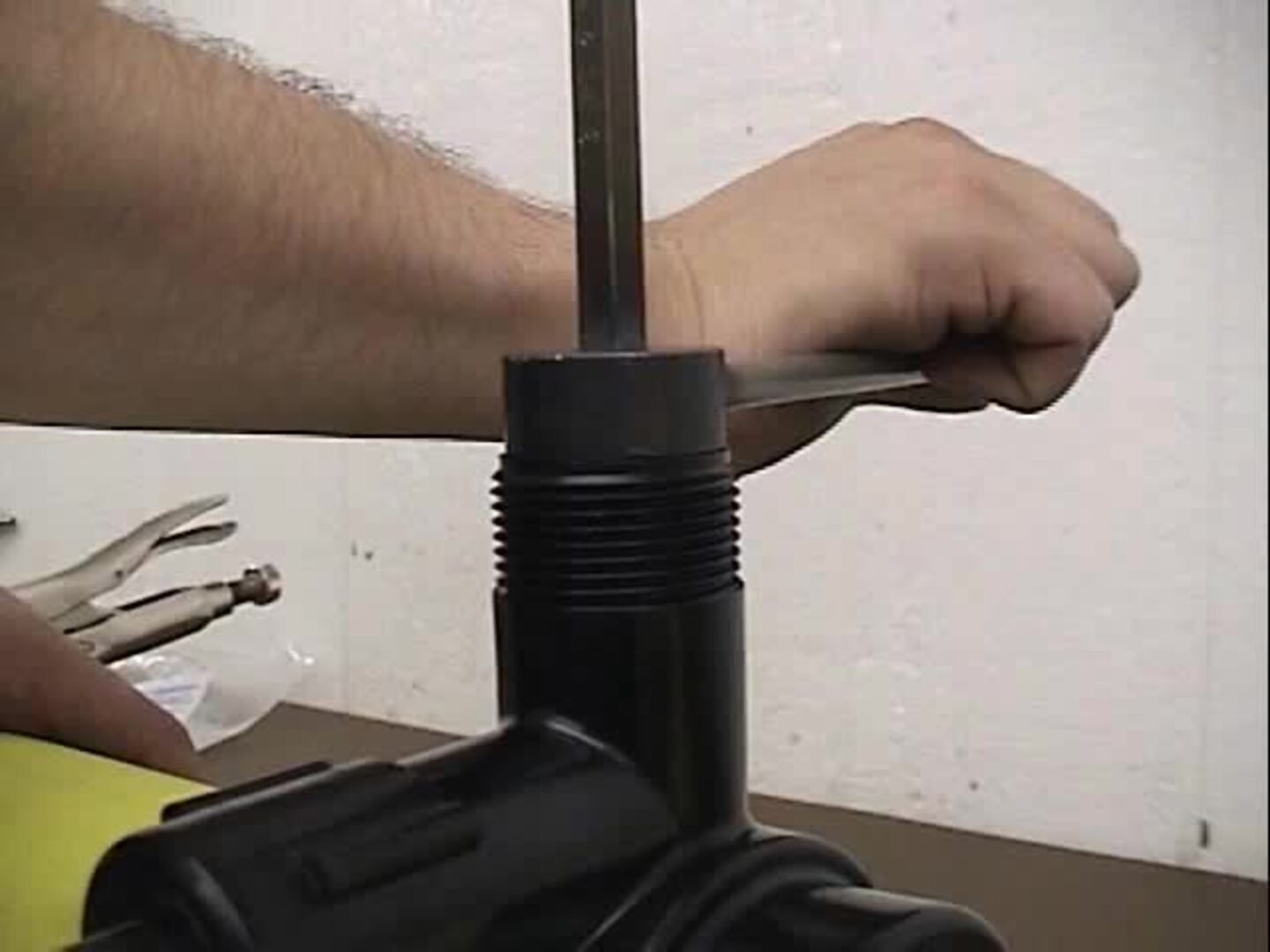
03:32Now remove the cap using Continental's tapping tool, insert the tool into the punch and screw
03:38down the punch until the stop on the tapping tool contacts the top of the t the tap is now
03:44complete to allow flow through the service back. The punch up until the top of the punch is
03:50flush with the top of the tee.
03:52It is important that the top of the punch does not protrude past the top of the T replace the
03:58cap and the installation is complete.
04:01The high volume tapping T or HVT comes with the installation instruction inside the bag.
04:07The bag contains the printed installation instructions, saddle top with compression
04:13outlet, saddle bottom with six mounting holes and the mounting bolt package containing six
04:19mounting bolts. The area where the saddle is to be installed
04:23must be clean and free of cuts and scratches. After the mounting surface has been prepared,
04:29place the top part of the saddle onto the pipe. Then the bottom part joining them together by
04:35hand. Remember that with this installation mount,
04:38the two center bolts. First of those two,
04:41there's one short bolt which mounts right underneath the outlet mate the saddle bottom to
04:47the saddle top against the pipe, placing and tightening the two bolts in the center holes
04:53first in a criss crossing motion, tighten the remaining bolts,
04:58making sure the saddle doesn't slip or turn on the pipe.
05:02Once you make sure the pipe is the proper size, be sure it is cut evenly and has a square edge
05:09mark the stab length on the pipe. According to the instructions,
05:13remove the red cap and the stiffener from the outlet without removing the compression nut.
05:21Compression nuts should be screwed in by hand until you see three or four threads in the back
05:26end place the stiffener into the pipe end until the neural of the stiffener meets the pipe end,
05:33then stab the pipe into the outlet up to but not past the mark.
05:39Tighten the compression nut by hand, then use a pipe wrench to finish tightening.
05:45The installation is complete when the compression nut shoulders up tight against the
05:50outlet leaving no space.
05:54Remove the cap and the O ring using Continental's tapping tool and the socket
05:59wrench screw the punch clockwise until the stop on the tapping tool contacts,
06:04the top of the T tapping is complete to allow flow to the service screw
06:11counterclockwise until the top of the punch is flush with the top of the T.
06:15It is important that the punch does not protrude above the T.
06:19Inspect the O ring for debris and clean if necessary.
06:24Replace the O ring, then replace and tighten the camp.
06:28The installation is complete compression connectors come
06:35with the instructions printed on the bag after making sure the pipe is cut
06:42square, make sure the ends are clean.
06:45Check the instructions for the proper stab depths and mark the pipes loosen the
06:51compression nuts until the seal rings are no longer compressed.
06:56Insert the pipe until it bottoms in the outlet, turn the compression nut hand tight,
07:03then use a wrench until it shoulders against the outlet.
07:06And there is no gap do not over tighten.
07:10The line marked for the stab depth should be no more than three quarters of an inch from the
07:15face of the compression nut repeat for the other end.
07:19Now, the installation is complete.

CONIND How to install Continental Industries compression connectors for gas
- private