I have noted the reprint of the N.E.C. (National Electrical Code), Article 450-4 in the question covering autotransformer overcurrent protection. Could you explain this article in detail by citing an example?
An example of an everyday application is always a good way to explain the intent of the “Code.”
Example: A 1 kVA transformer Catalog No. T111683 has a primary of 120 x 240V and a secondary of 12 x 24V. It is to be connected as an autotransformer at the time of installation to raise 208V to 230V single phase.
When this 1 kVA unit is connected as an autotransformer for this voltage combination, its kVA rating is increased to 9.58 kVA (may also be expressed as 9,580 VA). This is the rating to be used for determining the full load input amps and the sizing of the overcurrent protect device (fuse or breaker) on the input.

When the full load current is greater than 9 amps, the overcurrent protective device (usually a fuse or nonadjustable breaker) amp rating can be up to 125 percent of the full load rating of the autotransformer input amps.

The National Electrical Code, Article 450-4 (a) Exception, permits the use of the next higher standard ampere rating of the overcurrent device. This is shown in Article 240-6 of the N.E.C.

A buck-boost transformer is suitable for connecting as an autotransformer. What is the definition of an autotransformer and how does it differ from an isolation transformer?
An autotransformer is a transformer in which the primary (input) and the secondary (output) are electrically connected to each other.
An isolation transformer, also known as an insulating transformer, has complete electrical separation between the primary (input) and the secondary (output).
This is illustrated in the drawing below:
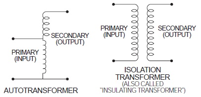
An autotransformer changes or transforms only a portion of the electrical energy it transmits. The rest of the electrical energy flows directly through the electrical connections between the primary and secondary. An isolation transformer (insulating transformer) changes or transforms all of the electrical energy it transmits. Consequently, an autotransformer is smaller, lighter in weight, and less costly than a comparable kVA size insulating transformer.
Please refer to this question for additional information on autotransformers. Buck-boost transformers are frequently field-connected as auto transformers.
When a buck-boost transformer is connected as an autotransformer such as boosting 208V to 230V, the kVA is greatly increased. What is the procedure for determining the size (ampere rating) of the overcurrent protective device such as a fuse or circuit breaker?
The National Electrical Code Article 450-4 addresses overcurrent protection of autotransformers. A copy is reproduced below for easy reference. 450-4. Autotransformers 600 Volts, Nominal, or Less.
(a) Overcurrent Protection. Each autotransformer 600 volts, nominal, or less shall be protected by an individual overcurrent device installed in series with each ungrounded input conductor. Such overcurrent device shall be rated or set at not more than 125 percent of the rated full-load input current of the autotransformer. An overcurrent device shall not be installed in series with the shunt winding (the winding common to both the input and the output circuits) of the autotransformer between Points A and B as shown in diagram 450-4.
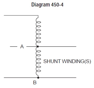
Exception: Where the rated input current of an autotransformer is 9 am peres or more and 125 percent of this current does not correspond to a standard rating of a fuse or non-adjustable circuit breaker, the next higher standard rating described in Section 240-6 shall be permitted. When the rated input current is less than 9 amperes, an overcurrent device rated or set at not more than 167 percent of the input current shall be permitted.
(b) Transformer Field-Connected as an Autotransformer. A transformer field-connected as an autotransformer shall be identified for use at elevated voltage.
Buck-boost transformers are almost always installed as autotransformers. Does the N.E.C. (National Electrical Code) permit the use of autotransformers?
Yes, please refer to N.E.C. Article 450-4, “Autotransformers 600 Volts, Nominal, or Less.” Item (a) explains how to overcurrent protect an autotransformer; item (b) explains that an insulating transformer such as a buck-boost transformer may be field connected as an autotransformer.
What is the life expectancy of a buck boost transformer?
The life expectancy of a buck-boost transformer is the same as the life expectancy of other dry type transformers.
Are buck-boost transformers as quiet as standard isolation transformers?
Yes, however, an auto-connected buck-boost transformer will be quieter than an isolation transformer capable of handling the same load. The isolation transformer would have to be physically larger than the buck-boost transformer, and small transformers are quieter than larger ones.
(Example) 1 kVA — 40 db; 75 kVA — 50 db. (db is a unit of sound measure).
Do buck-boost transformers present a safety hazard usually associated with autotransformers?
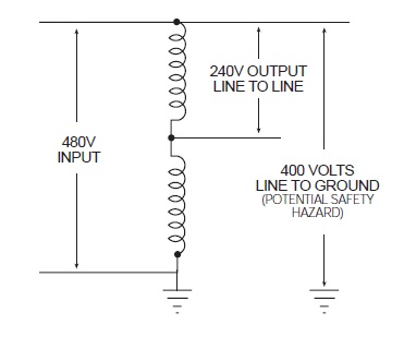
No. Most autotransformers, if they are not of the buck-boost variety, change voltage from one voltage class to another.
(Example 480V to 240V) In a system where one line is grounded, the user thinks he has 240V; yet due to the primary and secondary being tied together, it is possible to have 480V to ground from the 240V output. A buck-boost transformer only changes the voltage a small amount, such as 208V to 240V. This small increase does not represent a safety hazard, as compared to a buck of 480V to 240V.
Why is the isolation transformer kVA rating shown on the nameplate instead of the autotransformer kVA rating?
The kVA rating of a buck-boost transformer when auto connected depends on the amount of voltage buck or boost. Since the amount of voltage buck or boost is different for each connection, it is physically impossible to show all of the various voltage combinations and attainable kVA ratings on the nameplate.
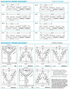
A connection chart showing the various attainable single phase and three-phase connections is packed with each unit.
Why are buck-boost transformers shipped from the factory as insulating transformers and not preconnected at the factory as autotransformers?
A four winding buck-boost transformer can be auto connected eight different ways to provide a multitude of voltage and kVA output combinations.
The proper transformer connection depends on the user’s supply voltage, load voltage and load kVA. Consequently, it is more feasible for the manufacturer to ship the unit as an insulating transformer and allow the user to connect it on the job site in accordance with the available supply voltage and requirements of his load.
What causes transformer noise, and how can it be eliminated?
Q: I am planning a new job which requires a 300 KVA, 3Ø transformer, several 25 KVA, 1Ø transformers and a 30 KVA, 3Ø transformer. This is essentially the same type of installation which our firm completed a year ago. In this installation we received numerous complaints about transformer noise. What causes transformer noise, and how can it be eliminated on the new job?
A: Transformer noise cannot be eliminated. It can, however, be reduced through proper design and assembly, and/or masked through proper consideration of the installation.
The basic cause of transformer noise is magnetostriction: the expansion and contraction of the iron core (laminations) due to the magnetic effect of alternation current flowing through the transformer coils. This produces an audible hum. Magnetostriction may be partially controlled by the transformer design, but it cannot be totally eliminated.
The fundamental sound frequency is twice the power line operating frequency of the transformer (i.e., a 50 Hz transformer produces sound at 100 Hz and a 60 Hz transformer produces sound at 120 Hz). In addition to the fundamental frequency, harmonics are also produced.
Since the average office environment is about 50 decibels, depending upon the equipment within the office, the location of a 300 KVA transformer in such an area would produce complaints. The 5 decibels (50db vs. 55db) difference between the normal office ambient sound level and the maximum sound level of the transformer may not seem significant; however, it is recognized that a 3 decibel increase in sound level measurement represents a doubling of the actual sound level, so the 5 decibel increase becomes quite large.
As this example shows, even a well designed transformer can be a problem if it is located without consideration of its surroundings. Transformer noise can be brought under control through proper installation. The following guidelines will help assure you of an acceptable installation.
1. The maximum sound level of the transformer to be used should be compared with the estimated ambient of its location. If it is higher than its estimated ambient, the unit should be relocated.
2. When installing transformers in “people areas”, such as office buildings or motels, plan to have at least one “non-people” room between the transformer and the “people area”.
3. The mounting surface for a transformer should not amplify the sound level. A general rule of thumb is the mounting base (such as a concrete floor) should weigh at least 10 times as much as the transformer.
4. A corner location should be avoided since the sound will be reflected out into the room.
5. Don’t mount unit on thin walls, such as plywood or curtain walls. They amplify the noise.
6. The manufacturer’s installation instructions should be followed so that any vibration suppression devices incorporated in the transformer design are utilized.
All Acme transformers operate at sounds levels below NEMA standards and each unit, 30 kVA and larger, is shipped from the factory with vibration isolation pads to help assure you of the quietest installation possible. Encapsulation greatly suppresses noise in units under 30 kVA, and vibration isolation pads are not required.
Can 60 Hertz buck-boost transformers be used on a 50 Hertz service?
No, Acme buck-boost transformers should be operated only at the frequencies recommended. However, units recommended for 50 cycle operation are suitable for 60 cycle operation but not vice versa.
How does the installer or user know how to connect a buck-boost transformer?
The connection chart packed with each unit shows how to make the appropriate connections. These same connection charts are also shown below.
Why isn’t a closed delta buck-boost connection recommended?
A closed delta buck-boost auto transformer connection requires more transformer kVA than a “wye” or open delta connection and phase shifting occurs on the output. Consequently the closed delta connection is more expensive and electrically inferior to other three-phase connections.
Should buck-boost transformers be used to develop a three-phase 4 wire Y circuit from a three-phase 3 wire delta circuit?
No, a three phase “wye” buck-boost transformer connection should be used only on a 4 wire source of supply. A delta to wye connection does not provide adequate current capacity to accommodate unbalanced currents flowing in the neutral wire of the 4 wire circuit.
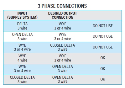
Can buck-boost transformers be used on three-phase systems as well as single phase systems?
Yes, a single unit is used to buck or boost single phase voltage — two or three units are used to buck or boost three phase voltage.
The number of units to be used in a three – phase installation depends on the number of wires in the supply line. If the three-phase supply is 4 wire Y, use three buck-boost transformers. If the 3-phase supply is 3 wire Y (neutral not available), use two buck-boost transformers.
Can buck-boost transformers be used on motor loads?
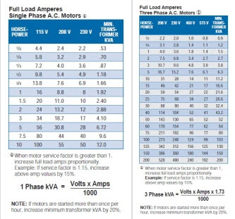
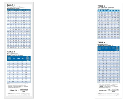
Yes, either single or three phase. Refer to the motor data chart below for determining kVA and Amps required by NEMA standard motors.
Why can a buck-boost transformer operate a kVA load many times larger than the kVA rating on its nameplate?
Since the transformer has been auto-connected in such a fashion that the 22V secondary voltage is added to the 208V primary voltage, it produces 230V output.
The autotransformer kVA is calculated:

For our example:

The picture to the below illustrates the difference in physical size between the autotransformer of 1 kVA, capable of handling a 9.58 kVA load, and an isolation transformer capable of handling a 7.5 kVA load.
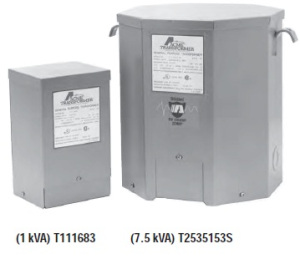
To cite an example… a model T111683 buck-boost transformer has a nameplate kVA rating of 1 kVA, but when it’s connected as an autotransformer boosting 208V to 230V, its kVA capacity increases to 9.58 kVA.
The key to understanding the operation of buck-boost transformers lies in the fact that the secondary windings are the only parts of the transformer that do the work of transforming voltage and current.
In the example above, only 22 volts are being transformed (boosted) — i.e. 208V + 22V = 230V. This 22V transformation is carried out by the secondary windings which are designed to operate at a maximum current of 41.67 amps (determined by wire size of windings).

For our examples:

Are there any restrictions on the type of load that can be operated from a buck-boost transformer?
No, there are no restrictions.
Will a buck-boost transformer stabilize voltage?
No. The output voltage is a function of the input voltage. If the input voltage varies, then the output voltage will also vary by the same percentage.
Why do buck-boost transformers have 4 windings?
To make them versatile! A four winding buck-boost transformer (2 primary and 2 secondary windings) can be connected eight different ways to provide a multitude of voltage and kVA outputs. A two winding (1 primary & 1 secondary) buck-boost transformer can be connected only one way.
Can buck-boost transformers be used to power low voltage circuits?
Yes, low voltage control, lighting circuits, or other low voltage applications requiring either 12V, 16V, 24V, 32V or 48V. The unit is connected as an insulating transformer and the nameplate kVA rating is the transformer’s capacity.
What are the most common applications for buck-boost transformers?
Boosting 208V to 230V or 240V and vice versa for commercial and industrial air conditioning systems; boosting 110V to 120V and 240V to 277V for lighting systems; voltage correction for heating systems and induction motors of all types. Many applications exist where supply voltages are constantly above or below normal.
Why are Buck-Boost transformers used?
Electrical and electronic equipment is designed to operate on standard supply voltage. When the supply voltage is constantly too high or too low, (usually more than 55%), the equipment fails to operate at maximum efficiency. A buck and boost transformer is a simple and ECONOMICAL means of correcting this off-standard voltage.
What is meant by “Balanced Loading” on Single Phase Transformer applications?
Since most single phase transformers have a secondary voltage of 120/240, they will be operated as a three wire system. Care must be taken in properly distributing the load as the transformer secondary consists of 2 separate 120 volt windings. Each 120 volt winding is rated at one-half the nameplate kVA rating.
For example: A 10 kVA transformer, 120/240 volt secondary is to service an 8 kVA load at 240 volts and two 1 kVA loads at 120 volts each.
If the incorrect method is used, winding A will be loaded at 6 kVA, and winding B will be loaded at 4 kVA. These do total 10 kVA but, since each winding is only rated at 5 kVA (1/2 of nameplate rating), we have an overloaded transformer and a certain failure.
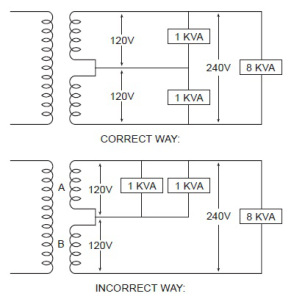
What about balanced loading on Three Phases?
Each phase of a three phase transformer must be considered as a single phase transformer when determining loading.
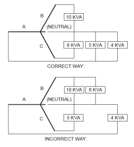
For example: A 45 kVA three phase transformer with a 208Y/120 volt secondary is to service 4 loads at 120 volts single phase each. These loads are 10 kVA, 5 kVA, 8 kVA,and 4 kVA.
NOTE: that maximum loading on any phase does not exceed 10 kVA. Each phase has a 15 kVA capacity.

If an incorrect method is used, phase B will have an 18 kVA load which is 3 kVA above its normal capacity of 15 kVA and failure will result even though we only have a total load of 27 kVA on a 45 kVA transformer.
Can 4-Winding Single Phase Transformer be auto-connected?
Yes. There are occasions where 480 volts single phase can be stepped down to 240 volts single phase by autoconnecting a standard 4- winding isolating transformer as shown below.If connected in this manner, the nameplate kVA is doubled.
For example: A 10 kVA load can be applied to a 5 kVA 4- winding transformer if connected see below.

Why are Small Distribution Transformers not used for Industrial Control Applications?
Industrial control equipment demands a momentary overload capacity of three to eight times normal capacity. This is most prevalent in solenoid or magnetic contactor applications where inrush currents can be three to eight times as high as normal sealed or holding currents but still maintain normal voltage at this momentary overloaded condition.
Distribution transformers are designed for good regulation up to 100 percent loading, but their output voltage will drop rapidly on momentary overloads of this type making them unsuitable for high inrush applications.
Industrial control transformers are designed especially for maintaining a high degree of regulation even at eight times normal load. This results in a larger and generally more expensive transformer.
How are transformers sized to operate Three Phase induction type squirrel cage motors?
The minimum transformer KVA rating required to operate a motor is calculated as follows:

NOTE: If the motor is to be started more than once per hour add 20% additional kVA.
Care should be exercised in sizing a transformer for an induction type squirrel cage motor as when it is started, the lock rotor amperage is approximately 5 to 7 times the running load amperage. This severe starting overload with result in a drop of the transformer output voltage. When the voltage is low the torque and the horsepower of the motor will drop proportionately to the square of the voltage.
Example: If the voltage were to drop by 70% of nominal, then motor horsepower and torque would drop to 70% squared or 49% of the motor nameplate rating.
If the motor used for starting a high torque load, the motor may stay at approximately 50% of normal running speed as illustrated by the graph below:
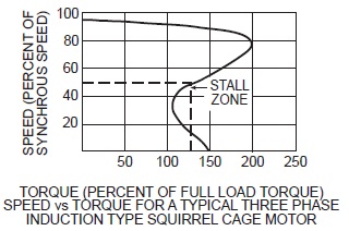
The underlying problem is low voltage at the motor terminals. If the ampere rating of the motor and transformer overcurrent device falls within the motor’s 50% RPM draw requirements, a problem is likely to develop. The overcurrent device may not open under intermediate motor ampere loading conditions. Overheating of the motor and/or transformer would occur possibly causing failure of either component.
This condition is more pronounced when on transformer is used to power one motor and the running amperes of the motor is in the vicinity of the full load ampere rating of the transformer. The following precautions should be followed:
1. When one transformer is used to operate one motor, the running amperes of the motor should not exceed 65% of the transformer’s full load ampere rating.
2. If several motors are being operated from one transformer, avoid having all motors start at the same time. If this is impractical, then size the transformer so that the total running current does not exceed 65% of the transformer’s full load ampere rating.
Can air cooled transformers be applied to motor loads?
This is an excellent application for air cooled transformers. Even though the inrush or starting current is five to seven times normal running current, the resultant lower voltage caused by this momentary overloading is actually beneficial in that a cushioning effect on motor starting is the result.
The tables below illustrate some typical transformer requirements for use with motor applications.
Will a transformer change Three Phase to Single Phase?
A transformer will not act as a phase changing device when attempting to change three phase to single phase. There is no way that a transformer will take three phase in and deliver single phase out while at the same time presenting a balanced load to the three phase supply system.
There are, however, circuits available to change three phase to two phase or vice versa using standard dual wound transformers.
Please contact the factory for two phase applications.
How do you select a transformer to operate in an ambient higher than 40° centigrade?
When the ambient exceeds 40°C use the following chart for de-rating standard transformers.

Instead of ordering custom built transformers to operate in ambients higher than 40°C, it is more economical to use a standard transformer of a larger KVA rating.
Can Single Phase Transformers be used for Three Phase applications?
Yes. Three phase transformers are sometimes not readily available whereas single phase transformers can generally be found in stock. Three single phase transformers can be used in delta connected primary and wye or delta connected secondary.
They should never be connected wye primary to wye secondary, since this will result in unstable secondary voltage. The equivalent three phase capacity when properly connected of three single phase transformers is three times the nameplate rating of each single phase transformer.
For example: Three 10 KVA single phase transformers will accommodate a 30 KVA three phase load.
Is one insulation system better than another?
Not necessarily. It depends on the application and the cost benefit to be realized. Higher temperature class insulation systems cost more and larger transformers are more expensive to build. Therefore, the more expensive insulation systems are more likely to be found in the larger KVA units.
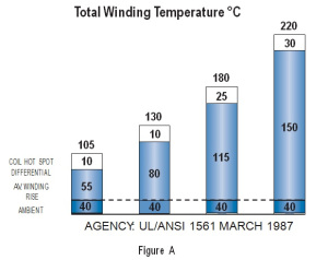
Referring to Figure A (Below), small fractional KVA transformers use insulation class 130°C. Compound filled Transformers use insulation class 180°C. Larger ventilated transformers are designed to use 220°C insulation. All of these insulation systems will normally have the same number of years operating life. A well designed transformer, observing these temperature limits, will have a life expectancy of 20-25 years.
Can 60 Hz transformers be used at higher frequencies?
Acme transformers can be used at frequencies above 60 Hz up through 400 Hz with no limitations provided nameplate voltages are not exceeded. However, 60 Hz transformers will have less voltage regulation at 400 Hz than 60 Hz.
What terminations are provided?
Primary and Secondary Terminations are provided on ACME Dry-Type Transformers as follows:
No lugs— lead type connection on:
1. 0-25 KVA single phase
2. 0-15 KVA three phase
3. Bus-bar terminations (drilled to NEMA standards)
4. 37.5 -250 KVA single phase
5. 25-500 KVA three phase
Can Transformers develop Three Phase power from a Single Phase source?
No, phase converters or phase shifting devices such as reactors and capacitors are required to convert single phase power to three phase.
Can a Single Phase Transformer be used on a Three Phase source?
Yes, any single phase transformer can be used on a three phase source by connecting the primary leads to any two wires of a three phase system, regardless of whether the source is three phase 3-wire or three phase 4-wire. The transformer output will be single phase.
Can Acme Transformers be reverse connected?
Acme dry-type distribution transformers can be reverse connected without a loss of KVA rating, but there are certain limitations.
Transformers rated 1 KVA and larger single phase, 3 KVA and larger three phase can be reverse connected without any adverse effects or loss in KVA capacity. The reason for this limitation in KVA size is, the turns ratio is the same as the voltage ratio.
Example: A transformer with a 480 volt input, 240 volt output— can have the output connected to a 240 volt source and thereby become the primary or input to the transformer, then the original 480 volt primary winding will become the output or 480 volt secondary.
On transformers rated below 1 KVA single phase, there is a turns ratio compensation on the low voltage winding. This means the low voltage winding has a greater voltage than the nameplate voltage indicates at no load.
For example, a small single phase transformer having a nameplate voltage of 480 volts primary and 240 volts secondary, would actually have a no load voltage of approximately 250 volts, and a full load voltage of 240 volts. If the 240 volt winding were connected to a 240 volt source, then the output voltage would consequently be approximately 460 volts at no load and approximately 442 volts at full load.
As the KVA becomes smaller, the compensation is greater— resulting in lower output voltages. When one attempts to use these transformers in reverse, the transformer will not be harmed; however, the output voltage will be lower than is indicated by the nameplate.
Can transformers be used in parallel?
Single phase transformers can be used in parallel only when their impedances and voltages are equal. If unequal voltages are used, a circulating current exists in the closed network between the two transformers, which will cause excess heating and result in a shorter life of the transformer. In addition, impedance values of each transformer must be within 7.5% of each other.
For example: Transformer A has an impedance of 4%, transformer B which is to be parallel to A must have an impedance between the limits of 3.7% and 4.3%.
When paralleling three phase transformers,the same precautions must be observed as listed above, plus the angular displacement and phasing between the two transformers must be identical.
Can a 60 Hz transformers be operated at 50 Hz?
Acme transformers, rated at 60 Hz, below 1 KVA can be used on 50 Hz service.
Transformers 1 KVA and larger, rated at 60 Hz, should not be used on 50 Hz service, due to the higher losses and resultant heat rise. Special designs are required for this service.
However, any 50 Hz transformer will operate on a 60 Hz service.
Can transformers be operated at voltages other than nameplate voltages?
In some cases, transformers can be operated at voltages below the nameplate rated voltage. In NO case should a transformer be operated at a voltage in excess of its nameplate rating, unless taps are provided for this purpose.
When operating below the rated voltage, the KVA capacity is reduced correspondingly.
For example, if a 480 volt primary transformer with a 240 volt secondary is operated at 240 volts, the secondary voltage is reduced to 120 volts. If the transformer was originally rated 10 KVA, the reduced rating could be 5 KVA, or in direct proportion to the applied voltage.