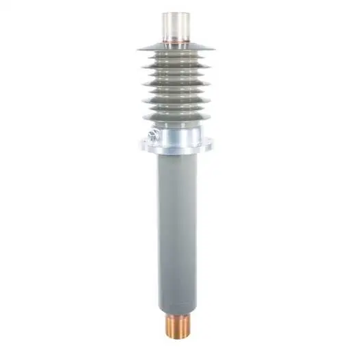
SDC™ Series, Composite Bushing - 28.4kV
Brand: Electro Composites
Catalog ID: 150-012-W-067-00
SDC™ 28.4kV-1200 A Wall/Floor Condenser Bushing, Solid-Dielectric-Capacitor Type, Rated per IEC 60137, Bottom Connected for Air-to-Air Applications, 10" Ground Shield/CT Pocket Length, 26.4" Min. Creepage Length
Electro Composites SDC™ composite bushings are designed to provide the toughest, cleanest and safest bushing solution for all HV applications. We make standard OEM and aftermarket form-fit-function replacement bushings for substation transformers, GSU transformers, oil circuit breakers, switchgear, wall/floor (air-air and oil-oil), HVDC and other applications. Available from 1kV up to 170kV with current ratings up to 21,500A. SDC™ (Solid Dielectric Capacitor) bushings have a one-piece cycloaliphatic epoxycore andtegral sheds. All SDC bushings are solid dielectricsulation – oil–free construction, capacitance graded condenser core withternal CT pocket/ground shield and a flange test tap, available bottom connected or draw-lead configurations. Made accordance with the most current bushing standards: IEEE C57.19.01, CSA C88.1, IEC 60137.
- SDC™ - Solid Dielectric Capacitance Graded Composite Construction
- EC-APG-02 Cycloaliphatic Epoxy Compound for Optimal Performance
- No oil, paper or porcelain
- Can be mounted vertically or horizontally
- Meets IEC 60137 Electrical and Mechanical Requirements
For Bushing Test Terminals, please see here
General
Application
Wall/Floor
Bottom Terminal Type
CONTACT DISC 1.50 DIA WITH 2X M8X1.25 HOLES ON 0.78 DIA BC
Catalog Number
150-012-W-067-00
Color
Gray
Flange Type
Epoxy
Immersion Type - Above Flange
Air
Immersion Type - Below Flange
Air
Material - Flange
Epoxy
Material - Insulation
APG-02 - Cycloaliphatic Epoxy
Mounting Position
Vertical to Horizontal
Number of Bolt Holes - Bottom Terminal
2
Number of Flange Mounting Holes
4
Plating - Bottom Terminal
Silver
Series
SDC™ Series
Test Tap
No
Top Terminal Type
1 1/2-12
Type
SDC - Solid Dielectric Capacitor
Dimensions
Above Flange Length
19 in
Below Flange Length
20.31 in
Depth
8.64 in
Diameter - Above Flange Maximum
8.64 in
Diameter - Below Flange Maximum D <gt/> 1"
4.49 in
Diameter - Below Flange Maximum P
5 in
Diameter - Conductor Outside Under Insulation
1.5 in
Diameter - Live Part Bottom
1.5 in
Diameter - Live Part Top
3 in
Diameter - Rod / Tube
1.5 in
Dimensions
39.31 in x 8.64 in x 8.64 in
Effective Length - Bottom Terminal
1.50 DIA in
Effective Length - Top Terminal
3.95 in
Flange Mounting Hole Bolt Circle
6.5 in
Flange Mounting Hole Diameter
1/2-13 in
Flange Outside Diameter
8.64 in
Height
8.64 in
Length
39.31 in
Length - Ground Shield
10 in
Length - Insulated Section
34.7 in
Length - Insulation Above Flange
14.6 in
Length - Insulation Below Flange
10.06 in
Length - Live Part Bottom
0.25 in
Length - Live Part Top
4.4 in
Sealing Surface Inside Diameter
5.43 in
Sealing Surface Outside Diameter
7.55 in
Thickness
1.495 in
Top Terminal Min. Thread Length
3.95 in
Weight
60 lb
Width
8.64 in
Electrical Ratings
BIL
150 kV
Current Rating
1200 A
kV Class
28.4 kV
Minimum Creepage
26.4 in
Minimum Creepage - Inside
28 in
Minimum Strike
16.52 in
Withstand Voltage - 60 Hz Dry
50 kV
Certifications And Compliance
Industry Standard(s)
IEC 60137
Operational
Immersion Type - Above Flange
Air
Immersion Type - Below Flange
Air
Configuration
Bottom Terminal Type
CONTACT DISC 1.50 DIA WITH 2X M8X1.25 HOLES ON 0.78 DIA BC
Mounting Position
Vertical to Horizontal
Number of Bolt Holes - Bottom Terminal
2
Number of Flange Mounting Holes
4