Transcript
00:04Welcome to the spice on connector. Overview, overview of termination process for
00:09the Hubble fiber hub splice on connector on 900 micro fiber hubble's fiber hub splice on
00:16connectors are an economical and reliable method for getting the best connection results
00:21for your fiber hubble's fiber hub splice on connectors are designed to maximize
00:26compatibility with all fusion splicer models in use today.
00:30Hubble's fiber hub splice on connectors are a fast and repeatable method to guarantee you
00:36have low loss and dependable connectivity in every installation,
00:40it is imperative to follow all safety guidelines for materials,
00:44tools and equipment. When working with optical fibers,
00:48safety glasses are a basic requirement. When working with optical fiber cleaved fiber
00:53scrap can be a hazard, wear safety glasses and discard glass fiber scrap in the appropriate
00:59safety container. It is recommended that you do not have open
01:03drinks or food in proximity of the fiber splicing workbench.
01:07Here are the items necessary for proper splice on connectors,
01:11termination, splice machine fiber strip tool to remove the tight buffer and
01:18accurate coatings down to just the glass fiber, use a precision strip tool to save labor splice
01:24on connector sled appropriate for your splicer, a precision cleaver such as the fiber hub,
01:30precision fiber optic cleave tool OFCLV five or equivalent is highly recommended duck
01:37bill or beaver tail style cleavers are not recommended as they will not afford the proper
01:42cleave quality field fiber to receive splice on connector.
01:47Scissors for cutting Kevlar or fiberglass. When accessing the cable for cleaning,
01:52optical fibers use lint free wipes and high grade cleaning solvent like 99% iso alcohol
01:59hubble's external oven is necessary for ST and FC type connectors and may be helpful for LC
02:06and SC type connectors.
02:09It is important to perform an arc calibration test to ensure the splicing machine is
02:14acclimated to working conditions, temperature elevation humidity,
02:18et cetera. It is recommended to use single mode fiber for
02:22arc calibration strip and clean two ends of a single mode fiber as you would normally
02:34cleave and place into the splicer clips.
02:55Choose your splicer's functions for arc power calibration and step through this process.
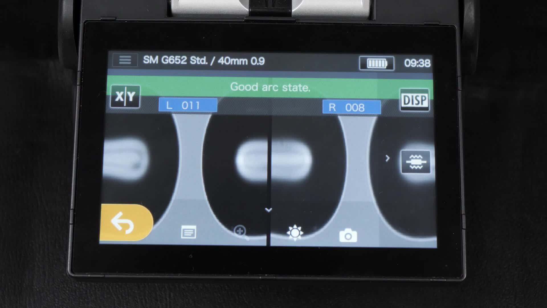
03:00If you see a result other than arc OK, or good arc state,
03:05you will need to repeat the arc test until this result is achieved.
03:09The splicer will automatically adjust if it finds the arc to be too weak or too strong.
03:15You may need to run the test again to get closer to the desired arc strength.
03:20It is not uncommon to run the arc test more than once to achieve the proper arc test result,
03:26set the fusion splicer's heater to the correct heater mode for the type of heat shrink you are
03:30using. These heat shrink sleeves are 27 millimeter
03:34setting. The heater for 40 millimeter is adequate to
03:37open the splice on connectors fold in half open from the back
03:45parts consist of the connector boot, the splice protection sleeve and the pre polished
03:50connector take the Hubble splice on connector carefully, remove the fiber protection by
03:56bending the protector away from the fiber. As shown place the connector into the sled or
04:01holder on the right side of the splicing machine.
04:04The setup should look as shown here before performing the splice.
04:08Notice the position of connector and sled slide. The 900 micron boot onto the field fiber
04:15slide, the 900 micron splice protection sleeve onto the field fiber
04:22next strip, the 900 micron jacket from the end of the field fiber by removing a quarter inch
04:28of tight buffer material at a time to a total stripped length of 1 to 1.5 inches.
04:39Wipe the fiber clean with cleaning solution and wipe before cleaving place the field fiber onto
04:46the splicer's removable 900 micron holder. Be sure to place the buffer to the end of the
04:51holder to ensure the proper cleave length of 10 millimeter
04:58cleave the fiber and place on the left side of the machine cleaved fiber end should extend
05:04right up to the splicer electrodes, close the splicer lid and prompt your splicer to continue
05:09through the splice process.
05:11Your estimated splice loss is now shown on screen.
05:14While insertion loss should be less than 0.3 DB per specifications.
05:19The estimated splice loss will typically be less than 0.03 DB and your actual splice loss
05:26will typically be closer to 0.00.
05:29The connector is now spliced onto the field fiber gently lift fiber from the field fiber
05:35side being aware that the splice could still break if handled incorrectly.
05:40Hold the assembly vertically as shown and slide protective sleeve down over the splice so that
05:45it goes right up against the connector as shown place the connector assembly into the oven so
05:51that the connector is inside the oven as shown here, press to close the lid.
05:56LC connectors may require a bit of force to close the lid.
05:59This is ok. Trigger your splicer to start the heating
06:03process if it is not set to do so, automatically gently remove assembly by slowly
06:09lifting from the field fiber side, hold the assembly as shown and slide the boot over the
06:14spice sleeve so that it goes right up against the connector.
06:17As shown. If you are working with sc connectors,
06:21you will now slide on the outer shroud. As shown here.
06:25Take your sc housing match up the key ways and slide it on.
06:29This requires a modest amount of force and there will be an audible click when it is in
06:34place. Process is now complete hubble's fiber hub
06:38splice on connectors will be a fast, convenient and reliable method to complete your projects
06:44with confidence.

Hubbell Premise Wiring FIBERHUBB Splice-On Connector Termination Process
- private