FAQs
Click on the faq's to open and close it.
This may vary widely depending on how your network is constructed and what else it is carrying, but as a general guide you will probably need:
- • A SIP proxy server (to route calls)
- • A SIP registrar server (frequently combined with the proxy server) to resolve URIs to IP addresses
- • A TFTP server (for downloading configuration files).
- • A TCP Syslog server (for reporting alarms and external inputs)
- • An SMTP server (for reporting via email)
- • An STNP server (to synchronise the internal clock)
- • A STUN server (for NAT firewall traversal)
Dedicated systems, such as Gatekeepers, VoIP-enabled PABXs or soft PABXs may also provide these functions. Bear in mind that GAI-Tronics telephones only support Session Initiation Protocol (SIP) to RFC3261, as opposed to H.323 or SCCP VoIP protocols for example.
Note that the performance of VoIP telephones depends on the provision of sufficient bandwidth and prioritisation on the network to give the quality of service required.
Let’s assume you have a telephone with 2 buttons: memory 1 for information, memory 2 for emergency. You want the emergency button to call “888” only. You want the information button to call the information desk, or if that is busy the security office, or failing that the administration center on 223344.
First set up the 4 possible user agents (end points) as memories on the memories page (it doesn’t matter which end point is in which memory):

Memory list 1 relates to memory button 1, and will dial memories 2, 3 and 4 in cascade.
Memory list 2 is for memory button 2, and will dial memory 1 only.
Note that, in this case, WAKEANDDIAL is set for both – the normal case for help point and hands-free telephones.
Refer to the Dialling & Memories pages in the Installation and User Guide for more details.
To do this you will need to set up email and/or syslog facilities within the phone, then set up the alarm itself, using the following 3 web pages:
- • Refer to the Email page to enter the required SMTP server settings for email.
- • Refer to the IP settings page to set up Syslog server settings.
- • Refer to the Alarms page to set which alarm events will report.

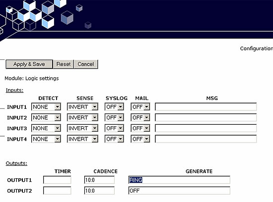
Traditional telephone beacons and sounders, with ring detectors, will not work on VoIP because there is no ring signal. You will therefore need a powered beacon or sounder instead, and use the telephone’s volt-free contacts to activate it. These beacons or sounders must be provided with a separate power supply – they cannot be powered from the telephone. Having connected an external device to an output (say Output 1), the next step is to set the output to activate it when required.

In this example, Output 1 is set to activate a flashing beacon, whilst Output 2 is set to activate a sounder in sync with the cadence of the ring signal (set on the Tone settings page). In both cases the outputs are energised when the phone is ringing with an incoming call, and de-energised when the call is answered or disconnected.
Refer to the Logic Settings page and Tone settings page in the Installation and User Guide for more details.
A common application is to have a single button hands-free telephone mounted outside a door, and a 15 button Commander model at a remote security point. Visitors arriving at the door use the hands-free unit to call the security point. A security guard answering the call can release the door lock by pressing the “R” button on the Commander unit.
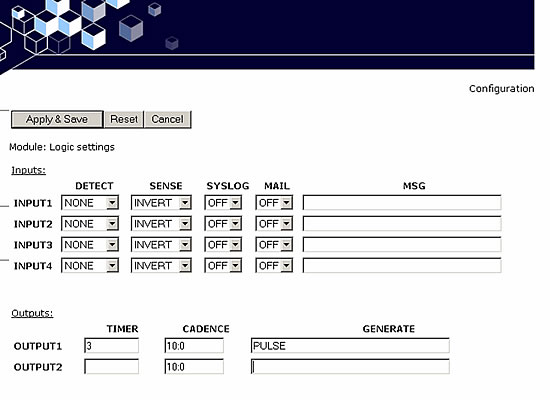
To achieve this, connect one of the volt-free outputs on the hands-free telephone (say output 1) to the electronic door release mechanism. Using the Logic settings page, set this output to PULSE:

Note that the TIMER is set to 3, meaning that the output will remain active for 3 seconds after being activated.
To activate this output from the security office, set the RECALL setting on the Key mapping page of the Commander unit to the IP address of the hands-free unit. So, for example, if the IP address of the hands-free were 192.168.9.2, the setting would be:

Refer to the Logic settings page and the Key mapping page in the Installation and User Guide for more details.
GAI-Tronics has the following weather and vandal resistant telephones available as VoIP:
WITH HANDSET
Commander – Plastic bodied telephone
Titan – Metal bodied telephone with door
Auteldac 4 – ATEX / IEC Zone 1 approved Hazardous Area telephone
HANDS-FREE
Public Access Help Point – Metal bodied, large metal button telephone, Braille, Inductive loop
PHP400 – Metal bodied, large metal button telephone, Braille, Inductive loop
7. How can I implement a Help Point system with GAI-Tronics VoIP products?
GAI-Tronics VoIP products incorporate a number of features designed to deliver a high-quality, resilient system across an IP network. This document highlights those features particularly important for implementing a Help Point or Emergency Call Point system.
There are two ways of setting the phone to make peer to peer calls.
The first is where there is no proxy server on the system at all. In this case:
- Set the ENDPOINT field on all of the SIP Info pages to DISABLED – do not enter any SIP proxy or registrar addresses on these pages.
- Make each entry on the Memories page the address of an endpoint or phone, in the form 1@192.168.1.2. Note that the number before the “@” symbol is not normally significant* – there just needs to be a number, followed by “@”, followed by the IP address of the end point.**
- Note that peer-to-peer calls can only be made by using a memory – not by manually dialling from a numeric keypad. All phones have at least one memory list (the OFFHOOK list). Refer to section 5.10 for details on setting up memories.
The second way is where one or more proxy servers are in use, but you want to be able to make a peer-to-peer call if no proxy is available. This is referred to as “failover to peer-to-peer”.In this case:
- Set the proxy address on one of the 4 SIP info pages (usually the one with the lowest priority) to be the IP address of an endpoint, in the form 192.168.1.2, but set the REGISTRAR address to be blank.
- If all attempts to make calls to higher priority proxies fail, the phone will attempt to place a call to this IP address as a peer-to-peer entity, regardless of what number is dialled or what entry is selected from a memory list.
NOTE: you cannot make a peer-to-peer call by entering an IP address on a numeric keypad – peer-to-peer calls can only be made using a memory dial.
*Some SIP phones may require this to be their phone number.
**Note, this could also be a FQDN (fully qualified domain name) if there is a DNS available on the network
If you are using GAI-Tronics CMA, simply set the PAGEMODE field (on the UNIT page) to “aa3”. CMA has a page button that will place a call to the unit in page mode, i.e. an announcement tone will be heard from the unit, following which the CMA operator will be able to make a page through the unit’s speaker.
It may be possible to activate this feature from systems other than CMA – contact GAI-Tronics for details.
Note page mode is usually implemented using handsfree models (VR and Help Point for example) but it may also be possible with other models, depending on application. The integral relays can also be set to activate during a page, and this feature could be used to trigger an external public address amplifier. Contact GAI-Tronics for details.
Requirements
- • A machine (PC) with a network connection to the VoIP unit
- • A TFTP server
- • GAI-Tronics VoIP Firmware package (see below)
Configure the TFTP Server
GAI-Tronics has performed successful firmware upgrades in the past using TFTP32, which can be found here:
http://tftpd32.jounin.net
Once the TFTP server has been installed it must be configured to have a root directory. Most GUI-based TFTP servers have a file path that can be set in a straightforward manner. Choose (or create) a directory on the host machine and configure the TFTP server to use this as the root directory.
Changing the firmware
[Download VoIP Firmware package here]
- Ensure the TFTP server is running, and visible on the network to the phone.
- Extract the following 4 files from the upgrade package and place them in the TFTP server’s working directory:
- a. uImage
b. incaip.root.jffs2
c. incaip.usrlocal.jffs2
d. Update.nfo - Edit Update.nfo (using Notepad for example) – change the IP address shown against “SERVER” to be the actual IP address of the TFTP server. Make sure that USERNAME and PASSWORD match the correct ones for the phone – defaults are “user” and “password”. Save Update.nfo.
- On the phone’s UNIT webpage, edit the SERVER field to be the address of the TFTP server. Edit the FILE field to be “Update.nfo” (without quotes). Apply & Save
- Click “Update Now” on the phone’s UNIT webpage
- You should see progress messages on the phone’s webpage showing each of the 3 image files (kernel, root fs and user fs) being erased, programmed and verified, then each of the image files being activated, then a reboot requested. This process takes about 5-10 minutes depending on the network. The TFTP server should also display the progress of the downloads.
- After the phone has rebooted, log back in to its Home page and confirm the firmware version (shown at the bottom of the page) is as expected. Update complete!