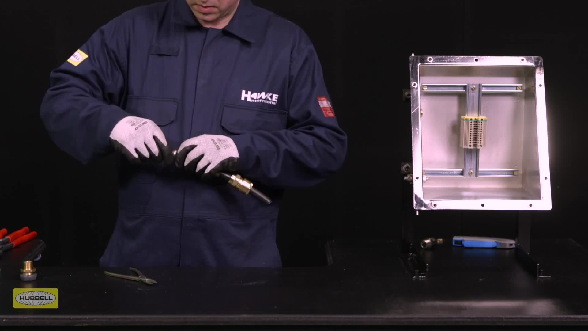
Transcript
00:07The 501453 universal cable. Gland consists of five key components,
00:13entry with deluge boot, diaphragm seal and armor spigot,
00:16reversible armor clamping ring, middle nut with patented tightening guide and back nut.
00:22This dual certified cable Gland is designed for use with all types of elastomer and plastic
00:27insulated cables including all types of armor and braid.
00:32The 501453 universal is especially suitable for cables that exhibit cold flow characteristics.
00:41Assembly instructions are provided with Hawk cable plans or can be downloaded by the Hawke
00:46website allow sufficient length of cable to suit the equipment.
00:51The cable is being terminated into strip the outer sheath and cut the armor to enable
00:57connection of the conductors to the terminal.
00:59Remove a further 20 millimeters of outer sheath for cable glands os to a size 25 millimeters
01:06for B to C two size and 32 millimeters for D to F size
01:12slide, the back nut, middle nut and armor clamping ring onto the cable ensure that the
01:19orientation of the reversible armor clamping ring is correct with the arrowhead indicating
01:24the correct armor braid or tape pointing to the equipment always refer to the Hawke assembly
01:31instructions for guidance on the correct armour clapping ring orientation tip.
01:36Alternative rings may be required if the cable does not fall within the R A CS standard
01:41clamping range, spread the armor or braid by gently pulling it away from the inner sheath of
01:47the cable. A screwdriver may be required for larger types
01:51of cables. Remove any plastic wrapping from the outside of
01:55the inner sheath, push the cable through the diaphragm seal.
02:01This action is aided by a pre fitted protective cap which removes the need to tape the
02:06conductors. This cap can be disposed of once the cable has
02:10passed through the seal.
02:12If the protective cap is not, there, tape may be used over the tip of the conductors,
02:18pull the diaphragm seal down the cable until the ends of the armor or braid are up to the
02:23spigot, shoulder slide, the entry component
02:30over the cable until the diaphragm seal is seated inside the entry slide,
02:35the middle nut up to the entry and hand tighten, support the cable to prevent it twisting,
02:46rip the entry with a spanner or wrench, use a second spanner or wrench to tighten half to
02:52three quarters of a turn
02:59unscrew the middle nut, the armour clamping ring should now be locked in place.
03:05Visually inspect that the armor or braid has been successfully clamped between the spigot
03:09and the armour clamping ring.
03:11If it isn't satisfactory repeat the previous steps, it required,
03:16fit the appropriate IP washer onto the entry thread, fit the entry into the enclosure and
03:22use a wrench to tighten, add a quarter turn with a wrench.
03:27Depending on the enclosure used, the method of installation will vary.
03:34Slide the cable through the entry hand, tighten the middle n to the entry and add a further
03:39quarter turn using a wrench
03:50hand, tighten the back nut until a seal is formed around the cable.
03:55Use a wrench or spanner to grip the middle nut while preventing the middle nut turning,
04:00use a second wrench to apply one further full turn to the back nut.
04:05Use our patented middle nut tightening guide as an indication that the bag nut is in the
04:10correct position to suit cable diameter tip.
04:14A diameter scale is provided in our assembly instructions to help with this process ensure
04:20that you have stripped the inner sheath to suit the application.
04:24The recommended exposure length of inner sheath is a minimum of five millimeters.
04:29Installation is complete.

Hawke 501453UNIV Cable Gland Installation Guide Hawke International
- private