Transcript
00:06The burnie aluminum terminal installation training video topics.
00:11We will discuss compression, terminal selection, wire, stripping,
00:14wire, insertion U dy selection crimping technique including number of crimps,
00:20crimp placement and crimping sequence inspection.
00:25Chapter one, proper connector selection, proper terminal selection is determined by the wire
00:30being terminated and the mounting requirements for the application.
00:34In this video, we are only focused on the wire termination portion of the terminal.
00:39Identify the wire material, copper or aluminum as this will determine the connector product
00:44line to be used to terminate. The wire wire types include copper solid wire,
00:49copper class B or C building wire and aluminum class B.
00:54Building wire, wire size or gauge will determine the physical wire size designation.
01:00Once the wire is identified, you can select the appropriate connector.
01:04This video will depict an installation using a four A awg aluminum terminal.
01:09For this video, we have selected an aluminum class B four A awg gauge wire installers can
01:16verify the proper connector by matching the wire size on the wire insulation to the
01:20connector. Barrel emboss Bernie aluminum lugs are dual
01:24rated and accommodate both aluminum class B and copper class B and C wire and have part number
01:31color code, dye index number, wire size markings and neural crimp bands embossed on the
01:36terminal barrel and or pad. The end cap color also corresponds to the dye
01:41color code. Chapter two proper wire stripping,
01:46wire insulation stripping is required for proper wire insertion into the connector.
01:51Proper wire stripping ensures full contact at each crimp with the wire.
01:55For optimal electrical and mechanical performance installers can find the wire strip
02:01link for the selected connector in the Burnie master catalog sales drawing or product label.
02:09If wire strip length is too long, it will expose bare wire between the barrel end and the
02:14insulation. While this does not pose a problem from an
02:17electrical or mechanical standpoint, it is not a recommended practice as exposed wires can
02:22pose a safety hazard.
02:24Wire that is exposed can be covered using burndy heat or cold shrink products.
02:30If wire strip length is too short, it will prevent the wire from fully inserting into the
02:34connector barrel preventing full crimps on the wire that could affect the integrity of the
02:39connection. When the strip length is properly sized,
02:42it ensures that no excess bare wire is exposed and the wire is fully inserted into the
02:47connector allowing four full cramps on the wire resulting in a safe and reliable connection.
02:52When stripping the insulation, be careful to avoid cutting or nicking wire strands as
02:57damaged strands can affect the integrity of the connection both from an electrical and
03:02mechanical standpoint chapter three, proper wire insertion before making a connection,
03:08verify proper wire strip length, hold the wire against the connector barrel.
03:13So the stripped insulation is budding. The barrel end visually verify the bare wire
03:18extends beyond the crimp zone as this ensures that the wire will be fully inserted into the
03:23barrel and will make full contact with the wire. When crimped wire brushing conductor is
03:28recommended for aluminum wire oxides can create an insulating barrier between the wire and
03:34connector that can minimize the conductivity in the connection for a less reliable connection.
03:40As a best practice wire brush all the conductor or wire before making a connection do not wire
03:46brush tin plated connectors.
03:48It is recommended to have an oxide inhibitor applied to aluminum conductor.
03:52So burn the aluminum connectors come prefilled with Petr A 13 oxide inhibitor and therefore
03:58are not available with an inspection window. Once the wire is scratch brushed,
04:03remove the color coded in cap and insert the wire into the connector until the wire can no
04:08longer be pushed in due to the aluminum connector barrels being prefilled with pet
04:13rocks, an installer may feel the wire stopped due to this oxide inhibitor.
04:17So the installer should apply enough force to sync the wire fully into the barrel.
04:22When this is done, excess pet rocks may discharge out of the terminal in chapter four,
04:27proper U die selection.
04:30The dy set will depend on the installation tool being used for this installation.
04:34We are using the 12 ton 750 series battery actuated Patriot T three tool which requires
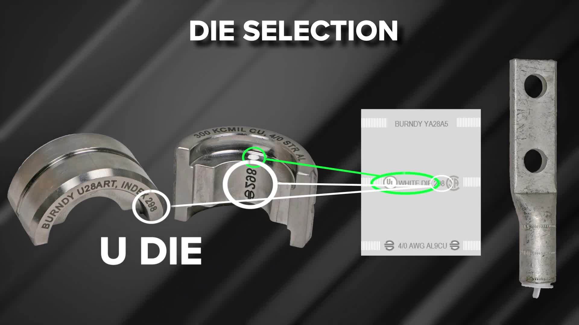
04:40you dyes when selecting the proper dy set installers can verify the dye with the
04:45connector by using the unique burnie dye index numbering system and color code,
04:51dye index number 298 and white color code for this installation indicates the following
04:57information can be verified before installation.
05:01Wire material can be aluminum or copper wire type is class B wire size is four
05:07oawg color code is white connector family is Y A 28 A burnie offers both
05:14aluminum and copper dis sets. So it is important that the proper dye is
05:18selected based on the material composition of the terminal being used regardless of if the
05:24wire being installed is aluminum or copper aluminum terminals require aluminum dye sets.
05:30Chapter five proper crimping technique, inserting dyes into the installation tool for
05:36the top die half, press the die release button at the top of the tool head slide,
05:41the dye half inside the tool head groove until it is centered.
05:44Release the dye button and wiggle the dye to ensure it is properly seated for the ra M or
05:49bottom die half, press the dye release button on the side of the ram slide,
05:53the die half inside the tool head groove until it is centered.
05:57Release the dye button and wiggle the dye to ensure it is properly seated.
06:01Once both die halves are properly seated in the tool head.
06:04You are ready for cramping installation process. Once the number of crimps,
06:09crimp location and crimping sequence has been determined, you can begin the installation
06:14Bernie installation manuals and the Bernie Connect app provide you with a number of crimps,
06:19crimp location, crimping sequence and crimping diagrams to get the Bernie installation
06:24instruction manuals or the free Bernie Connect mobile app,
06:28go to the resources tab on the Bernie website to demonstrate proper
06:35crimping technique. We will be crimping an aluminum four oawg
06:38terminal with four oawg aluminum wire. We are going to show the crimping procedure for
06:44a four oawg aluminum terminal for this installation that can requires two crims place
06:51the connector against the top die haft with the bottom of the terminal pad facing the lower die
06:57haft. The top dye is stationary during tool
07:00activation allowing the installer to maintain proper connector alignment.
07:04During crimping align the first crimp closest to the terminal pad with the center of the
07:09crimp die between the 1st and 2nd embossed neural bands as shown in the illustration begin
07:15the tool's crimping cycle tool indicates a full cycle has been completed when an audible pop
07:20sound is heard. Some tools also depict a green indicator light
07:26as a secondary indicator of a completed crimp.
07:29A red light would indicate an incomplete crimp.
07:33Once the first crimp is complete, retract the tool ramp and align the second crimp closest to
07:38the wire end with the center of the crimp dye between the 3rd and 4th crimp bands as shown in
07:43the illustration. Once you have finished your two crimps,
07:46the installation is complete, you can verify that a proper installation has been made by the
07:51presence of the correct dye emboss on the connector falling within the crimp zones.
07:57The crimping orientation during an installation on a seamless compression terminal is not
08:02critical from an electrical or mechanical performance perspective.
08:06However, crimping in the orientation recommended provides a uniform and clean
08:10looking connection crimping. Contrary to birdie's recommendations may cause
08:15flash to extrude vertically on the terminal which could prevent the connector from sitting
08:19flush on mounting surfaces.
08:23Chapter six, proper inspection inspectors can validate proper terminal installation with the
08:29use of U dyes visually and physically visual inspection inspectors can visually see the
08:36dye index number embossed on each crimp of the connection.
08:39Dye index emboss provide the inspectors with wire material,
08:43either copper or aluminum wire type. In this example,
08:47class B wire size. In this example, for a awg dy index number on
08:54the emboss matches with the markings on the terminal.
08:56In this case, 298 color code in this instance, white and connector family.
09:02In this example, Y A 28 A as indicated on the terminal emboss
09:09inspection with physical measurement tools.
09:12Physical inspection of A crimp can be done with the use of the wire mic C I or calipers,
09:17wire mic C I can be used as a you dye post primp measurement tool.
09:21Place the wire mic on the crimp, read the dye catalog number indicated on the tool and verify
09:27that dye catalog number with the dye used based on the dye index number and color code.
09:32The Burnie Connect app provides the post print dimension range place calipers on the prim and
09:38verify the readings fall within the proper post print dimensions.
09:42This concludes the aluminum terminal installation training video.

Burndy Aluminum Compression Terminal Installation Video
- private
- electrical contractor
- electricalcontractor