Take a TourHere is a glimpse of Burndy’s Solutions for the different Markets.
Take a TourA quick look through the various markets we are equipped to cater to: browse Burndy Markets
Transcript
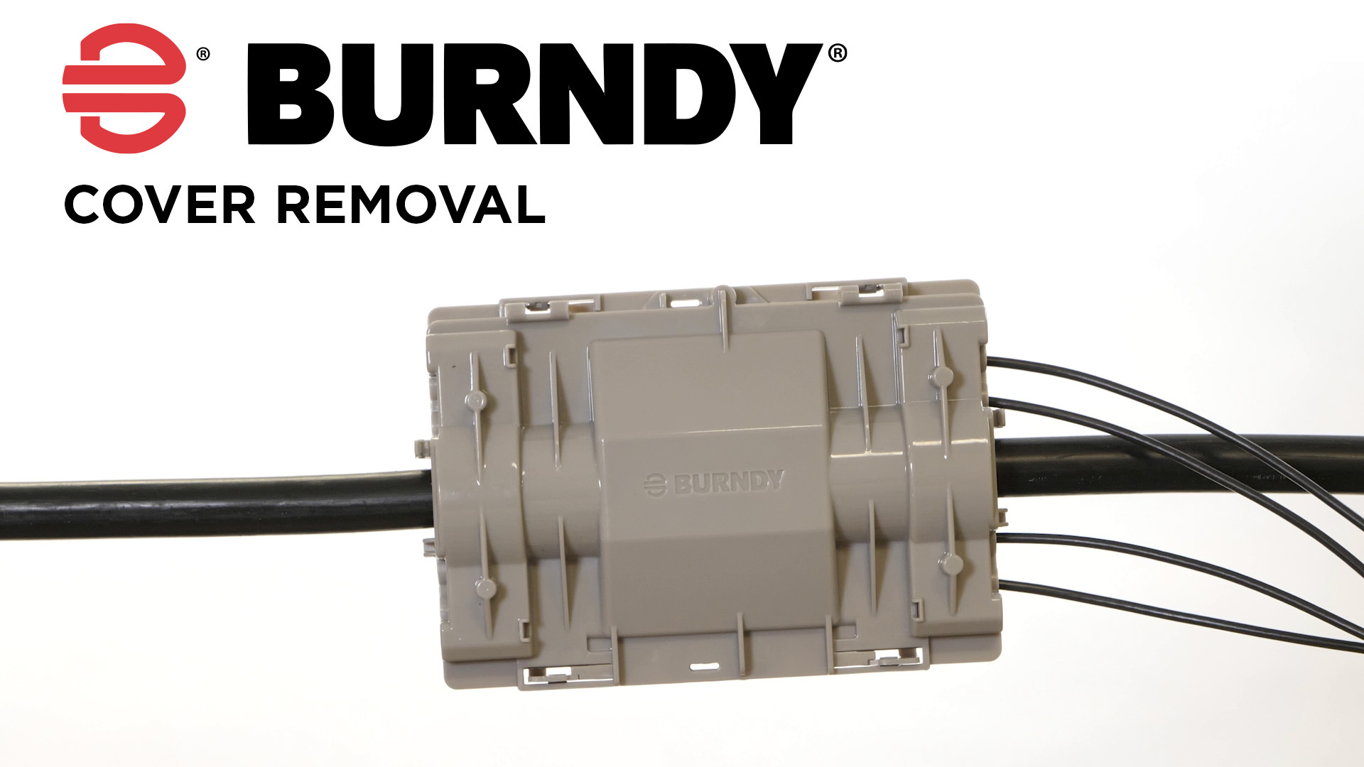
00:11The burnie aluminum insulation piercing compression connector cover removal,
00:15video topics we will discuss unlocking the outer cover and unlocking the strain relief
00:21locking handle for full cover removal.
00:24Due to the water tight seal cover removal and reuse is not permitted by burnie covers are one
00:30time use products and any warranty is void if covers are reused.
00:35If a cover removal is necessary, a new cover will be required.
00:39Chapter one, unlocking the outer cover.
00:43The outer cover has eight locking features, four locking tabs at wire entry and two locking
00:49tabs on each side of the cover.
00:51Step one, unlock the four wire entry tabs by inserting 42 inch long one quarter inch
00:57diameter peg insulated wire or like item between the four wire entrance tabs releasing
01:03the locking features.
01:04For this example, the installer is using 42 inch eight A WG PV wire strips as pegs
01:19step two using a flathead screwdriver slide, the flathead under the side locking flap and
01:26lift to open
01:43step three while the locking flap is being held open, push the locking tab toward the cover,
01:49releasing the lock, you can release the locking flap after and it should rest on the locking
01:54tab remaining unlocked step four, repeat steps two and three for the other side,
02:00locking tab located on the same side of the cover.
02:03Step five, unlocking both tabs on the same side will create a separation gap between the cover
02:09halves at the wire entry on both sides.
02:12For each side slide the flat head in the gap and twist,
02:15releasing the locking tab.
02:17Step six repeat steps two through five for the locking tabs on the other side of the cover
02:24step seven. Once all locking tabs are interlocked,
02:27you can remove one cover half chapter two, unlocking the strain relief locking handle for
02:33cover removal, step one place a two inch long one quarter inch diameter peg screwdriver
02:40insulated wire or like item under the strain relief locking handle and push down.
02:45So the peg applies an upward force on the handle.
02:49Do not release the pressure on the item, apply pressure to the handle until the locking handle
02:54is fully unlocked. In this example, I'm using a two inch eight A
02:58WG PV wire step two while maintaining pressure on PV wire under the handle
03:05slide, a flathead screwdriver into one of the two handle lock release slots and rotate the
03:10screwdriver until the handle unlocks on that side.
03:14Repeat steps one through three on the other strain relief locking handle.
03:24Step four for both sides, open the handle and the upper strain relief and remove the cover
03:30from the connector.
03:39This concludes the insulation piercing compression cover removal video.
03:44For more information about insulation piercing compression connector product solutions scan
03:49the QR code, visit the Bernie website or contact customer service.
03:54Thank you for watching.
Understand how to properly remove the cover of our Compression Insulating Piercing Connector. For more information on this innovative product visit our website: https://www.hubbell.com/burndy/en/solutions/solar-trunk-bus