Transcript
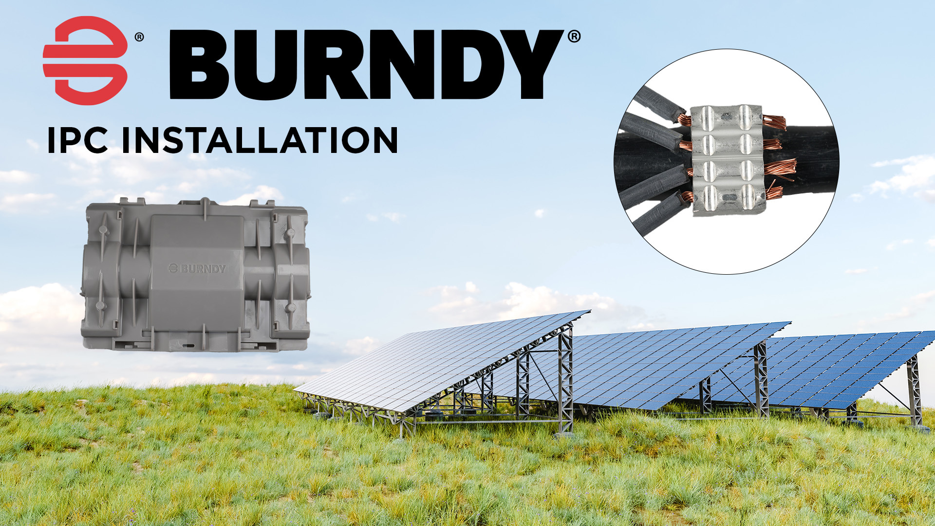
00:11The burnie aluminum insulation piercing compression connector.
00:14Installation video topics we will discuss product material overview,
00:18connector selection, tap wire, stripping, dye selection, dye insertion connector,
00:24installation cover installation, chapter one product material overview.
00:31Before we get started, be sure you have the following materials.
00:35Installation instructions prior to installation installers are required to read and understand
00:40the installation instructions proper compression connector.
00:45Two plastic cover halves one half with strain relief devices and the other half without
00:49strain relief. Proper Bernie Crimp dye set for the connector,
00:53see soy sales drawing or catalog page for proper dy set selection,
00:58proper Bernie installation tool identified in the installation instructions.
01:03Chapter two proper connector selection, proper connector selection is determined by the wire
01:09accommodates for the application. As this will determine the actual connector to
01:13be used. In this video, we will be installing A Y I PC
01:1734 8 CWC connector for this connector. The main run conductor accommodates a 500
01:24KC mill aluminum compact stranded PV wire rated two KV and 90 °C.
01:31The tap wire accommodates 10 A WG copper compact or concentric seven or 19 stranded PV
01:37wire rated two KV and 90 °C chapter three, proper wire stripping.
01:44The main run trunk wire does not require wire stripping as the connector is designed with
01:49insulation pierce features.
01:51The tap wires require installation stripping to ensure optimal electrical and mechanical
01:56performance. Proper wire strip length is identified in the
02:00installation instructions provided with the product and the sales drawing or master catalog.
02:06When stripping the insulation, be careful to avoid cutting or nicking wire strands as
02:10damaged strands can affect the integrity of the connection both from an electrical and
02:14mechanical standpoint.
02:16Chapter four proper dye selection.
02:19The P dye sets are unique for this product line and designed for the 15 ton 46 series crimp
02:25tool platform. The P dye selection will depend on the
02:29connector being installed for the Y I PC 34 8 CWC.
02:34The required upper dye will be the P I PC 34 U and the required lower dye will be the P I PC
02:4134 LP Dy fit in Bernie's 15 ton 46 series crimp tools.
02:46Bernie recommends our T three version. So installations can be tracked,
02:50traced and transmitted for connection validation.
02:55Chapter five, proper die insertion for the lower dye half press the dye pin release button
03:01on the side of the tool head slide, the lower dye into the tool head aligning the dye holes
03:07with the tool locking pins, release the dye pin button and wiggle the dye to be sure it is
03:12properly seated for the upper dye press the dye pin release button at the top of the tool head
03:18slide, the upper dye into the tool head aligning the dye holes with the tool locking
03:22pins, release the dye pin button and wiggle the dye to be sure it is properly seated.
03:28Once both die halves are properly seated in the tool head,
03:31you are ready for crimping chapter six connector installation before making a
03:37connection, verify that the tap wires have been properly stripped,
03:41hold the strip tap wires against the connector. So the stripped insulation is budding.
03:45The connector side visually verify the bare wire extends beyond the connector by a quarter
03:51inch as this ensures that the wire will be fully inserted into the connector and has
03:56enough exposed wire to be bent upward, holding the tap wires in place during installation,
04:01insert each tap wire fully into the connector.
04:05After inserting each wire into the connector, use a pair of pliers and bend the exposed wire
04:10ends up as much as 90 degrees preventing the wires from slipping out of the connector during
04:15installation
04:28before installing the connector on the main run conductor.
04:32Be sure the connector orientation is correct as this orientation will dictate the cover
04:37orientation as a recommendation. If you are installing the connector in an
04:42application with no parallel wiring or horizontal space constraints orientation,
04:46one is acceptable if you are installing the connector in an application with parallel
04:51wiring and space constraints. Orientation two is recommended orientation one,
04:57if you see the connector on the trunk conductor vertically as shown,
05:01the cover width will be installed parallel to the ground
05:09orientation two.
05:10If you see the conductor on the trunk conductor horizontally is shown,
05:14the cover width will be installed perpendicular to the ground.
05:19For this demonstration, we will be installing the connector based on orientation one seat,
05:25the connector over the trunk conductor resting the three piercing teeth on the conductor.
05:29As shown seat, the connector in the dye set be sure.
05:33The connector is pushed against the lower dye backstop.
05:36Once the connector is properly seated in the dyes begin the tools crimping cycle
05:51tool indicates a full cycle has been completed when an audible pop sound is heard
06:02due to the compressive forces in the dyes from the connector.
06:05Installers need to shift the tool head to the side releasing the connector from the dyes.
06:11Some tools also depict a green indicator light as a secondary indicator of a completed crim.
06:17A red light would indicate an incomplete crim chapter seven cover installation.
06:24When removing the plastic packaging from the covers, do not tear the packaging.
06:28As some of the plastic could make contact with the gel,
06:31we want to avoid displacing or damage the gel seat.
06:34If any plastic comes into contact with the gel, peel the plastic away from the gel slowly and
06:39the gel will set back into place, start with the cover half that has the locking handles and
06:44strain relief devices as shown open the locking handles and upper strain relief arms align the
06:51cover to the connection by main run wire will seat in the covers,
06:55main run alignment guides on each side align the connector.
06:59So it seats inside the connector, alignment guides bend the tap wires above the main run
07:04connector. So they don't get in the gel while seating the
07:07connector in the cover slide, the connector into the cover be sure.
07:12The main run wire is in the alignment guides and firmly push the main run wire into the gel.
07:17If the tap wires are coming out one end only lock the strain relief on the end with no tap
07:23wires to do this first, close the upper strain relief on the wire and then close the handle on
07:29the upper strain relief.
07:31Press the handle into the upper strain relief until it locks into place.
07:35The cover will be secured to the wire.
07:37So you can let go and work on routing the tap wires into the other end of the cover seed.
07:43Each tap wire in the gel, making sure each wire is properly routed in the cover and strain
07:48relief wire alignment grooves
08:02close the upper strain relief on the wires and then close the handle on the upper strain
08:06relief. Press the handle into the upper strain relief
08:09until it locks into place.
08:12Take the other cover half without the strain relief and install,
08:16align the cover orientation by aligning the post and holes with the other cover seat.
08:21The cover on the other cover half by mating the alignment posts and holes and locking tabs
08:27firmly snap into place all eight locking tabs on all four sides.
08:36Once all locking tabs are snapped into place and secure,
08:39your installation is complete.
08:41This concludes the insulation piercing compression connector.
08:45Installation video.
08:46For more information about installation piercing compression connector product
08:50solutions scan the QR code, visit the Bernie website or contact customer service.
08:56Thank you for watching.

BURNDY’s Compression IPC Installation Instructions
Watch as we easily and safely install our Compression Insulating Piercing Connector. Learn more about this innovative product by visiting our website: https://www.hubbell.com/burndy/en/solutions/solar-trunk-bus
- private
- burndy youtube
- ipc
- burndy
- compression
- utility
- connector
- piercing