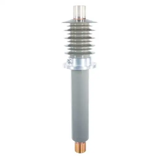
SDC™ Series, Composite Bushing - 34.5KV
Brand: Electro Composites
Catalog ID: 200-001-W-898-00
SDC™ 34.5kV-100A Wall/Floor Condenser Bushing, Solid-Dielectric-Capacitor Type, Rated per IEEE C57.19.01, Bottom Connected for Air-to-Air Applications, 1.0" Ground Shield Length, 34.6" Min. Creepage Length
Electro Composites SDC™ composite bushings are designed to provide the toughest, cleanest and safest bushing solution for all HV applications. We make standard OEM and aftermarket form-fit-function replacement bushings for substation transformers, GSU transformers, oil circuit breakers, switchgear, wall/floor (air-air and oil-oil), HVDC and other applications. Available from 1kV up to 170kV with current ratings up to 21,500A. SDC™ (Solid Dielectric Capacitor) bushings have a one-piece cycloaliphatic epoxycore and integral sheds. All SDC bushings are solid dielectric insulation – oil–free construction, capacitance graded condenser core with internal CT pocket/ground shield and a flange test tap, available in bottom connected or draw-lead configurations. Made in accordance with the most current bushing standards: IEEE C57.19.01, CSA C88.1, IEC 60137.
- SDC™ - Solid Dielectric Capacitance Graded Composite Construction
- EC-APG-02 Cycloaliphatic Epoxy Compound for Optimal Performance
- No oil, paper or porcelain
- Can be mounted vertically or horizontally
- Meets IEEE C57.19.01 Electrical and Mechanical Requirements
For Bushing Test Terminals, please see here
General
Application
Wall/Floor
Bottom Terminal Type
3/8-16
Catalog Number
200-001-W-898-00
Color
Gray
Immersion Type - Above Flange
Air
Immersion Type - Below Flange
Air
Material - Flange
Aluminum
Material - Insulation
APG-02 - Cycloaliphatic Epoxy
Mounting Position
Vertical to Horizontal
Number of Flange Mounting Holes
4
Series
SDC™ Series
Test Tap
No
Top Terminal Type
3/8-16
Type
SDC - Solid Dielectric Capacitor
Dimensions
Above Flange Length
17.05 in
Below Flange Length
14.75 in
Depth
6.25 in
Diameter - Above Flange Maximum
7.47 in
Diameter - Below Flange Maximum D <gt/> 1"
2.98 in
Diameter - Below Flange Maximum P
3.1 in
Diameter - Conductor Outside Under Insulation
0.75 in
Diameter - Live Part Bottom
0.75 in
Diameter - Live Part Top
2.25 in
Diameter - Rod / Tube
0.75 in
Dimensions
31.8 in x 6.25 in x 6.25 in
Effective Length - Bottom Terminal
1 in
Effective Length - Top Terminal
2 in
Flange Mounting Hole Bolt Circle
5.5 in
Flange Mounting Hole Diameter
0.5 in
Flange Outside Diameter
6.25 in
Height
6.25 in
Length
31.8 in
Length - Ground Shield
1 in
Length - Insulated Section
28.5 in
Length - Insulation Above Flange
11.2 in
Length - Insulation Below Flange
12.37 in
Length - Live Part Bottom
1.38 in
Length - Live Part Top
2.59 in
Sealing Surface Inside Diameter
3.16 in
Sealing Surface Outside Diameter
5 in
Thickness
1.115 in
Top Terminal Min. Thread Length
2 in
Weight
35 lb
Width
6.25 in
Electrical Ratings
BIL
200 kV
Current Rating
100 A
kV Class
34.5 kV
Minimum Creepage
34.6 in
Minimum Creepage - Inside
13.2 in
Minimum Strike
13.8 in
Minimum Strike - Inside
13.2 in
Withstand Voltage - 60 Hz Dry
80 kV
Certifications And Compliance
Industry Standard(s)
IEEE C57.19.01
Operational
Immersion Type - Above Flange
Air
Immersion Type - Below Flange
Air
Configuration
Bottom Terminal Type
3/8-16
Mounting Position
Vertical to Horizontal
Number of Flange Mounting Holes
4